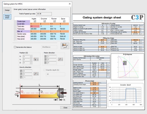
The HPDC Gating Design Wizard simplifies gating design by allowing users to input casting details like weight, projected area, material, shot machine, and biscuit size. It generates a PQ graph to verify the shot machine's capability, and provides key results like filling time, ingate velocity, required ingate area, and phase velocities and shift times. The wizard also calculates casting pressure, clamping force margins, and runner cross-sections for use in Smart Runner Design. This streamlined process ensures an efficient, accurate, and quick gating design, reducing the time and effort required for setup.

Gating Wizard Main UI
Runners and Shot Sleeve Design
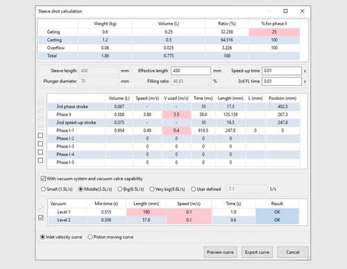
Phase Parameters and Vacuum Design
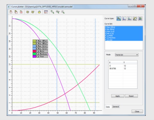
PQ Graph Analysis